CANA-4 · the setup page
Set up from a phone
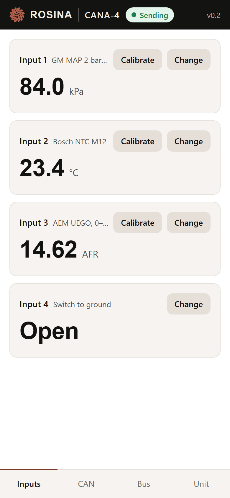
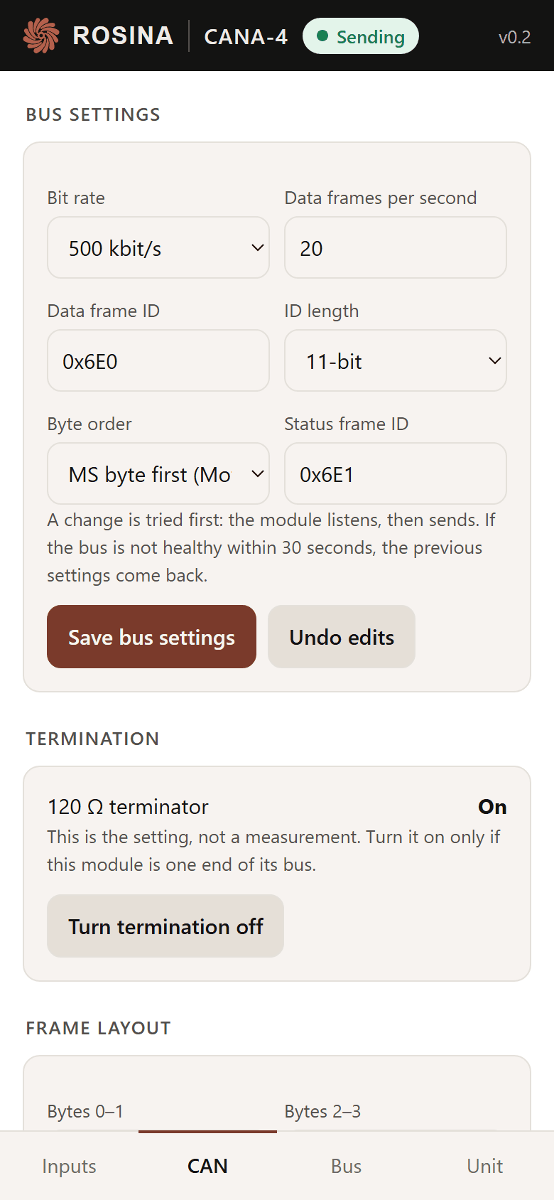
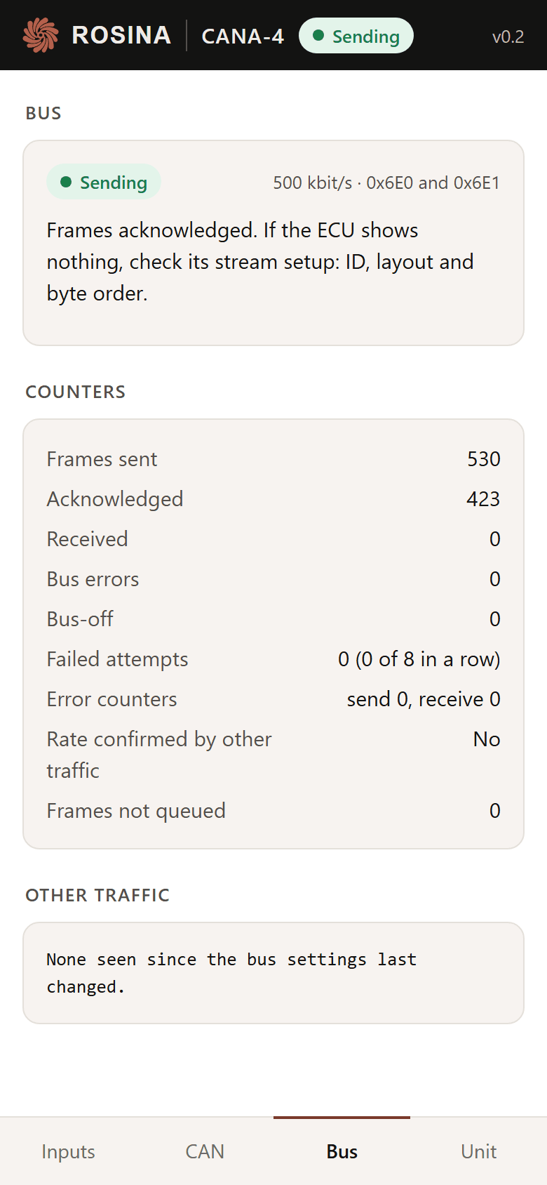
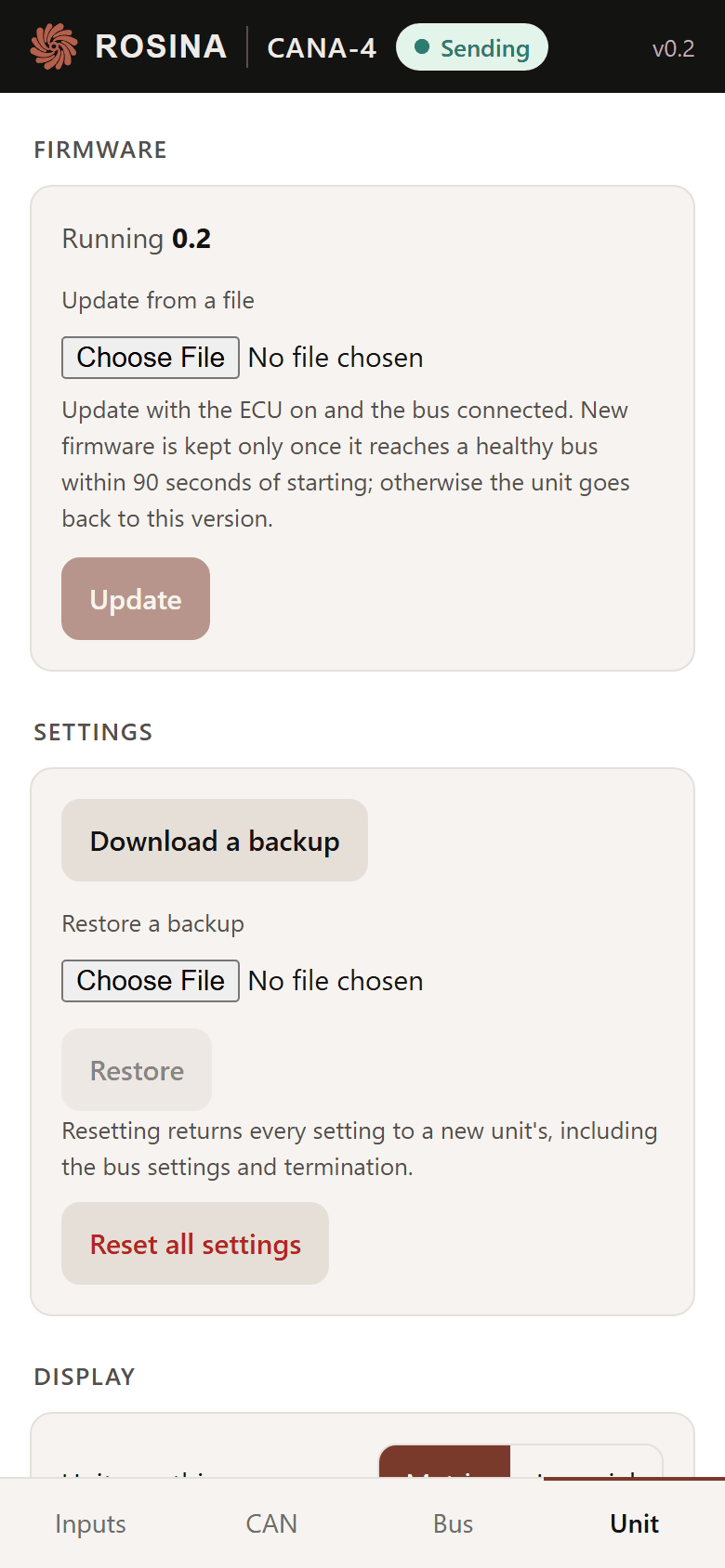
The module carries its own WiFi and its own page. Every setting an ECU could ask for is on it: the bit rate, the identifiers, the byte order, what each input is wired to and what it should read. No app, no cable, no laptop in the engine bay. These are the page's own screens, drawn by the firmware a unit runs.
The page
First run, then four tabs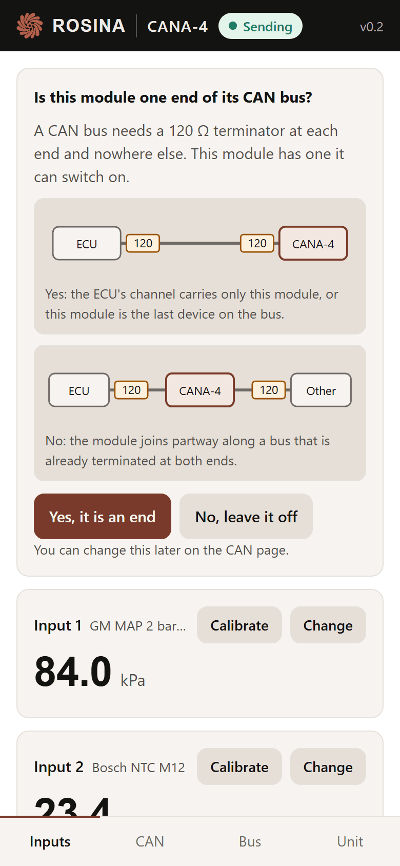
How it works
- Its own network. Power the module and its WiFi, CANA-4- followed by four characters, is up for 5 minutes. It stays up while a phone is connected, and the page can close it.
- Its own password. Each unit has one, WPA2, printed on its label.
- Nothing to install. The page opens by itself when a phone joins the network. On a later visit, 192.168.4.1 in any browser.
- A change is tried before it is kept. A new bit rate or identifier goes out on probation; if the bus never acknowledges it, the module undoes it after 30 seconds, so a typo cannot take a bus down.
- Updates over the same page. A new firmware image that does not reach a healthy bus is undone automatically.
The EGA5 and EGA12 have no page. They are amplifiers: two calibration points in your ECU's own software, and the setup guides walk each platform through it.
Why one module reads on any ECU: CAN, plainly. The rest of the module: specs and wiring.